Baxi Eco 3 Wartungshandbuch
Stöbern Sie online oder laden Sie Wartungshandbuch nach Warmwasserbereiter & Kessel Baxi Eco 3 herunter. Baxi Eco 3 Technical data [en] Benutzerhandbuch
- Seite / 44
- Inhaltsverzeichnis
- LESEZEICHEN
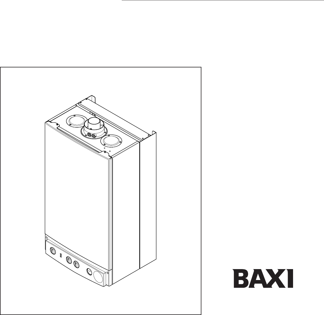
- Baxi Combi 80Eco 1
- Natural Gas 2
- Contents 3
- 1.0 Introduction 4
- 2.0 General Layout 5
- 3.0 Appliance Operation 6
- 4.0 Technical Data 7
- 5.0 Dimensions and Fixings 8
- Dimensions 8
- 6.0 System Details 10
- 7.0 Site Requirements 12
- IRING REGULATIONS 13
- FIXING TEMPLATE 17
- 4 in valve with 18
- 8.0 Installation 19
- 9.0 Commissioning the Boiler 22
- 10.0 Completion 24
- 11.0 Servicing the Boiler 25
- 12.0 Changing Components 27
- Control PCB 36
- 14.0 Fault Finding 37
- 15.0 Short Parts List 42
- After Sales Service 44
- 08706 096 096 44
- Technical Enquiries 44
- 08706 049 049 44
Inhaltsverzeichnis
Baxi Combi 80Eco Gas Fired Wall Mounted Combination BoilerInstallation and Servicing InstructionsPlease leave these instructions with the user
StopValveDoubleCheckValveDHWMainsInletCHReturnTemporaryHose6.0 System Details106.5 System Filling and Pressurising1. A filling point connection on the
6.0 System Details116.8 Domestic Hot Water Circuit1. All DHW circuits, connections, fittings, etc.should be fully in accordance with relevantstandards
7.0 Site Requirements127.1 Information1. The installation must be carried out by a CORGIRegistered Installer or other registered competentperson and b
7.0 Site Requirements137.5 Ventilation of Compartments1. Where the appliance is installed in a cupboardor compartment, no air vents are required.2. BS
7.0 Site Requirements14Fig. 167.8 Flue1. The flue terminal position must be inaccordance with the current editions of B.S.5440 Part 1, and either Part
7.0 Site Requirements157.9 Flue DimensionsThe standard horizontal flue kit allows for fluelengths between 100mm and 1metre from elbowto terminal (Fig.
167.0 Site Requirements7.12 Flue Options1. The Baxi Combi 80Eco can be fitted with fluesystems as illustrated. 2. The standard flue is suitable only f
8.0 Installation178.1 Initial PreparationThe gas supply, gas type and pressure mustbe checked for suitability before connection(see Section 7.6).1. Af
8.0 Installation188.4 Fitting The Boiler1. Lift the boiler using the lower edges. Engagethe slots at the top rear of the boiler on the wallplate hooks
8.0 Installation198.6 Fitting The FlueHORIZONTAL FLUE1. The standard flue is suitable for lengths100mm minimum to 1m maximum (measuredfrom the edge of
2Baxi UK Limited is one of the leading manufacturersof domestic heating products in the UK. Our first priority is to give a high quality service to o
8.0 Installation208.6 Fitting the Flue (Cont)IMPORTANT: If the equivalent flue length isgreater than 1.5m the restrictor MUST beremoved from the adapt
8.0 Installation218.7 Making The Electrical ConnectionsTo connect the mains input cable proceed asfollows:-1. Slacken the facia securing screws and li
9.0 Commissioning the Boiler229.1 Commissioning the Boiler1. Reference should be made to BS 5449 Section5 when commissioning the boiler. 2. Open the m
9.0 Commissioning the Boiler239.2 Checking the Burner Pressure1. Turn on the gas and electrical supplies to theboiler and ensure that all external con
10.0 Completion2410.1 Completion1. Hinge the facia panel upwards and refit thecase front panel. Secure them with the screwspreviously removed (Fig. 45
11.0 Servicing the Boiler2511 .1 Annual Servicing1. For reasons of safety and economy, it isrecommended that the boiler is serviced annually.Servicing
11.0 Servicing the Boiler2611.1 Annual Servicing (Cont)10. Remove the spring clips retaining the air boxside baffle plates. Disengage the tabs on theb
12.0 Changing Components27IMPORTANT: When changing componentsensure that both the gas and electricalsupplies to the boiler are isolated before anywork
12.0 Changing Components2812.3 Heat Exchanger (Fig. 62)1. Note the positions of the two sensing tubes onthe outlet elbow and three wires on the fan mo
12.0 Changing Components2912.5 Injectors (Fig. 64)1. Remove the burner as described in Section12.4.2. Undo the screws securing the injectormanifold to
31.0 Introduction 42.0 General Layout 53.0 Appliance Operation 64.0 Technical Data 75.0 Dimensions and Fixings 86.0 System Details 97.0 Site Requireme
12.0 Changing Components3012.8 Gas Valve (Fig. 66)1. Undo the nut on the gas feed pipe at the tap railunder the boiler.2. Remove the securing screws a
12.0 Changing Components3112.11 Pump - Head Only (Figs. 68 & 69)1. Drain the primary circuit and remove thesocket head screws securing the pump he
12.0 Changing Components3212.14 Pressure Gauge 1. Drain the primary circuit and undo the nut onthe pressure gauge capillary (Fig. 71).2. Remove th
12.0 Changing Components3312.17 Pressure Relief Valve (Fig. 78)1. Drain the primary circuit.2. Disconnect the discharge pipe from the valve.Using a su
12.0 Changing Components3412.20 Plate Heat Exchanger (Fig. 81)1. Drain the primary circuit.2. While supporting the heat exchanger undo thescrews secur
12.0 Changing Components3512.21 Diverter Valve Assembly (Cont)Pressure Differential Valve (Fig. 84)1. Remove the pressure differential valve asdescrib
13.0 Illustrated Wiring Diagram36Optional TimersPumpGas ValveAir Pressure SwitchSafety ThermostatHydraulic DifferentialPressure SwitchTemperature Sens
14.0 Fault Finding37Carry out initial fault finding checks1. Check that gas, water and electrical supplies are available at the boiler. Electrical sup
14.0 Fault Finding38Domestic Hot Water - Follow operational sequenceTurn selector to neon illuminatedPrimary flow switchoperatedFan runs at max sp
14.0 Fault Finding39Fault Finding Solutions Sections A to EIs there 230V at:Is there 230V at:Main terminals L and N Check electrical supply1.NOMain te
Baxi UK Limited declare that no substancesharmful to health are contained in theappliance or used during appliancemanufacture.1.1 Description1. The Ba
14.0 Fault Finding40Check and correct if necessary1. Electrical and pressure tube connections2. Blockage of pressure tubes3. Restriction in flue4. Ven
14.0 Fault Finding41Check and correct if necessary1. Flame sensing electrode and lead connections2. Electrode positionFlame current should be 1 µA app
15.0 Short Parts List42Short Parts ListKey G.C. Description ManufacturersNo. No. Part No.22 E66 383 Fan 24800123 393-497 Pressure Switch 2
43Baxi UK Limited manufacture a comprehensive rangeof products for the domestic heating market.Gas Central Heating Boilers(Wall, Floor and Fireside mo
Baxi UK LimitedBrownedge RoadBamber Bridge PrestonLancashirePR5 6SNwww.baxi.comAfter Sales Service08706 096 096Technical Enquiries08706 049 049Comp No
2.0 General Layout52.1 Layout1. Air Pressure Switch2. Expansion Vessel3. Burner Manifold4. Automatic Air Vent5. DHW Plate Heat Exchanger6. Circulation
3.0 Appliance Operation6NOTE: All delay timers mentioned in 3.1 and3.2 are overridden by domestic hot waterdemand.3.1 Central Heating Mode (Fig. 4)1.
4.0 Technical Data7Flue Terminal Diameter 100mmDimensions Projection 95mmOutercase DimensionsCasing Height - 780mmOverall Height Inc FlueElbow - 980mm
5.0 Dimensions and Fixings8DimensionsA 780mmB 345mmC 450mmD 107mm Ø Min.E 200mmF 190mmG 143mm360° Orientation Tube Ø 100mmDCBAEGF65mm 65mm 65mm 65mmWa
6.0 System Details96.1 Information1. The Baxi Combi 80Eco Combination Boiler is a‘Water Byelaws Scheme - Approved Product’.To comply with the Water By
Weitere Dokumente für Warmwasserbereiter & Kessel Baxi Eco 3


Verwandte Produkte und Handbücher für Warmwasserbereiter & Kessel Baxi Eco 3
 (31 Seiten)
© 2020, manymanuals.de. Alle Rechte vorbehalten. | 1.526 s |
 Manymanuals.com
 Manymanuals.de
 Manymanuals.fr
 Manymanuals.it
 Manymanuals.pl
 Manymanuals.cz
 Manymanuals.es
 Manymanuals-pt.com
Kommentare zu diesen Handbüchern